Vehicle Detection Loop Circuit

Induction Loop Vehicle Detector

Vehicle Loop Detector

Vehicle Loop Detector 2
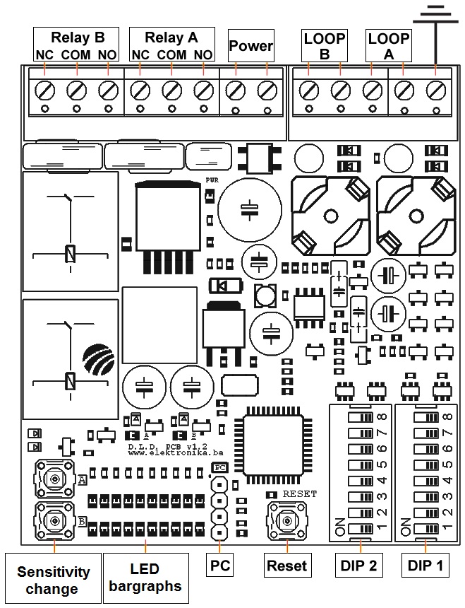
Dual Channel Inductive Loop Vehicle Detector Elektronika Ba
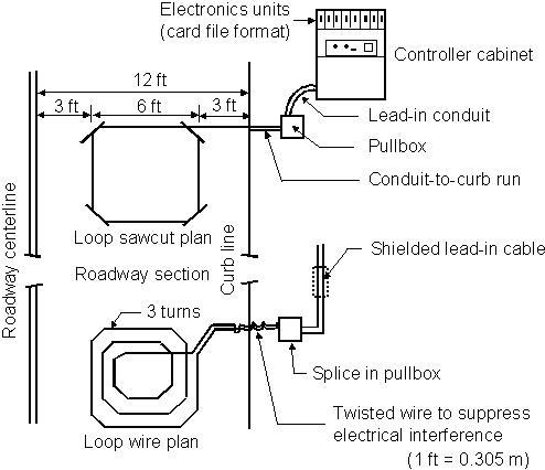
Chapter 1 Traffic Detector Handbook Third Edition Volume I Fhwa Hrt 06 108
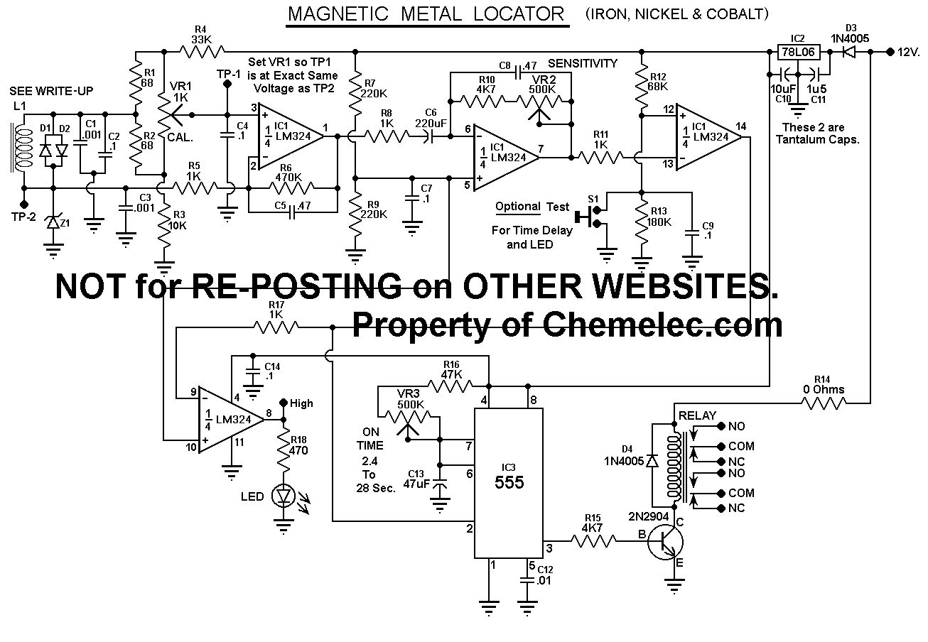
Vehicle Magnetic Metal Detector

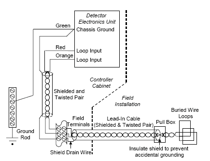
Is a block diagram of a vehicle detector circuit according to the invention for the induction loop vehicle detector description of the induction loop vehicle detector referring to fig.
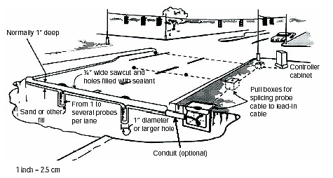
Vehicle detection loop circuit.
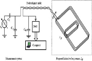
Fuzzy Based Traffic Congestion Detection Pattern Analysis Using Inductive Loop Sensor
Chapter 2 Traffic Detector Handbook Third Edition Volume I Fhwa Hrt 06 108
Traffic Detector Handbook Third Edition Volume Ii Fhwa Hrt 06 139
Http Www Trb Org Conferences Natmec 2004 15 Inabnitt Pdf
Source : pinterest.com
